I figured it was time to build on a new project. First I was thinking of making a SW transmitter at around 10 watts carrier but MW bit me again and I am more of a local broadcast type of pirate anyways. Though SW is fun Well first I started with a SW 5-9MHz VFO but the circuit just wasn't working out as planned. I went with a basic cookie cutter VFO schematic on the web using two FETs, one for the osc and another as a buffer, then a bipolar npn as the second buffer. It worked as said for chirp problems associated with CW, but the carrier would drift on me after a good hour. So I set out to redesign and build my own crap rather then go with anything else. So I want a new MW rig that covers 1500-1750. This way I can broadcast on basic US MW BCB and still cover a bit into SW 160m band if the AM dial gets crazy.
Well the very first part of this project is obviously the VFO. I don't have the luxury to buy crystals for MW bands. Even if I were to, I like to be able to shift frequency since the AM bands here are messy and stations pop up sometimes w/o warning, and also because I like to experiment. So a VFO is the way to go. I have used many hartly oscillators in my past designs. They work well and are easy to get up and running. The problem with those designs is they tend to be drifty. So for this VFO I went with the Clapp type. I like this simple design because the coil needs no tap. Best of all if I had to I could use "plug-in" coils, or just use a large coil and tap it to the general coverage frequency and then use a varicap for main tune around that.
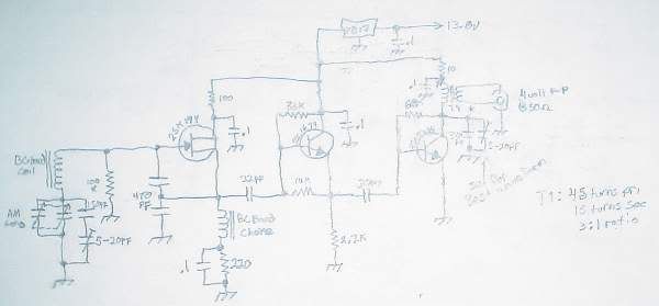
So that was the plan, a VFO that covers 1500-1710 or so. Well here is my crappy but really good design taken right from the notebook lol... (neat pics will come soon) Sorry if you can't see the writing the best, like said better pics soon, this is just a draft.
Well the VFO has 4 to 6 volt p-p pure sign wave output into a 50ohm load (a bit more unloaded) or around 500mw (1/2 watt) on average. In fact the signal is so clean it blows me away. The first harmonic doesn't even pick up on my radio unless I put the darn thing RF input full blast right next to the tank coil! I wanted a pure clean sign wave and this VFO not only cuts it, but it does it like a champ. I have never designed a VFO in my life that has a signal of PURE sign and almost no harmonic content. I would feel safe running this thing into a small few watt linear w/o even worrying about a filter and trust me I am a strictler when it comes to that kind of thing.
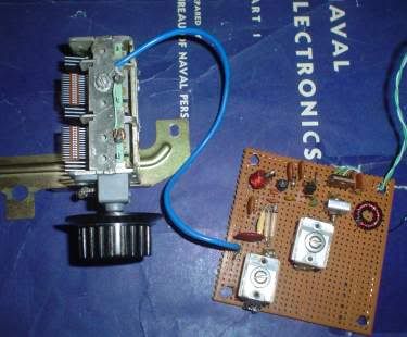
Here is a pic of the actual board...
The book in the background probably deserves it's own description but I will leave that to your imagination. The board is a reused perf board from a project that failed once taken from bread to perf board (we've all been there right?).
The varicap is a general AM MW type from an old stereo.
Next up, a 2-4 watt linear broadband, then a 10 watt (probably tube) PA with modulator circuit and negative clip circuit and heising modulation or at least that is the goal.
I plan to use a 12BQ6 tube as the PA, or maybe a pair if I decide to go push pull since I have a few of these old sweep tubes laying around and they work great for HF PAs up to around 40 watts carrier (remember I am aiming for 10 watts carrier, 40 watts modulated).
Much more to come in the future. Keep tuned in. I really hope this will be the do all kill all project that will get my pirate station heard by even a few of you guys on 1710kHz (1610 is my normal spot with my current LP rig).
edit: forgot to say how stable this thing is on frequency as is. Only slight drift on warm up, after a few mins it's rock solid, only w/o the rock Even when putting any kind of load, even short circuit on the output it only drifts a slight bit to the ear whilst listening to it against a receivers BFO. In other words, that 4v p-p output is crazy solid.
Few notes I forgot in case people can't read the crappy picture or are curious about design notes.. Transistors from left to right... 2SK19 (Y type) as FET osc. Most FETs would work equally well but all these transistors came from an old CB circuit board as scraps, 2SC1674 as first buffer, 2SC2314 as second buffer/vfo amp. The FET can be any type really. It's the second two bipolar transistors that tend to have a very bipolar mood. In other words the second two have resistance values around them to bias them just right to achive a perfect signwave and most other types probably wouldn't work right for my circuit.
The main osc coil is a MW choke actually. I found this out of an old MW radio. The MW RFC is probably the same value as the osc coil ( used three 3mHz chokes in series for my setup). The output transistor probably seems rather robust for only 1/2 watt but trust me that extra leway is worth it. The trimmer capacitor connected to the output transistors collector to ground is to make the signwave look pretty. Tune to a nice 360 on a scope.
This thing could be modulated as is for a great part 15 transmitter. Just disconnect the output transistor from the 10ohm resistor and the 12 volt regulator and insert your modulation circuit. Series modulation would work okay and get you right around 100mw with no noticable AM wobble or other stupid issues most experience with kit type transmitters and talking signs aka crap.
Oh one more thing, I didn't use a clamp diode on the FET. Why in the hell do people use them in the first place? Sure it makes the thing slightly more stable and same voltage over a variation of frequency but in my opinion it's not worth the extra stages if you design it right. I just don't get why people use clamp diodes on the gate. Can anyone fill me in here? It only made my test designs fail at producing anything clean or worthy for RF output to drive PAs.


 ~~~~~~~~~~~~~~~~~~~~~~~~~~~~~
 ~~~~~~~~~~~~~~~~~~~~~~~~~~~~~