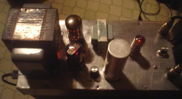
Just finished building this piece of gear for my 1 watt FM exciter. Gives a clean 8-10 watts output with around 1 watt input. Uses a 7551 tube that originally came out of an old aircraft transceiver set built in the 60s. This tube was also used in many mobile communications back in the day so it's really durable. There is a 6.3 volt version with the number 7558 that is more common but I used what I had.
In operation at full power. RF meter reading about 11 watts at 1.5 SWR..
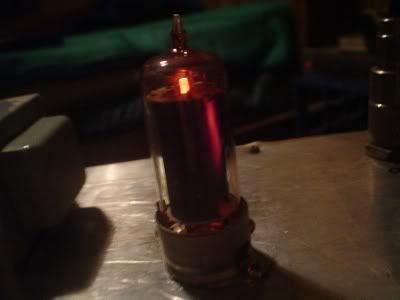
Hot 7551, even at a foot distance you can feel the heat...
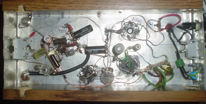
Guts...
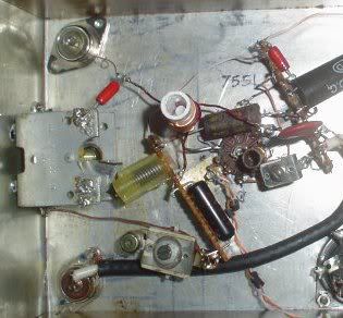
Just RF section of guts more magnified.. Funny note, I got my fingers a little too close to that RF coil when tuning up and felt that RF hit my finger like a bee sting. Ouch. Take a 12 volt light bulb and take the two leads and turn it into a coiled loop and place around the RF coil and it glows nice and bright
And finally, schematic (drawn with stencil)...
Works like a charm. Thinking of mounting the whole thing into a metal box and fanning it through since the 20 watt resistor and the tube/ps transformer gets mighty warm.
With my 1 watt exciter and this 10 watt amp I am getting about 2 miles solid coverage with a cheap walkman that has horrible selectivity, about 5+ miles with a good radio and possibly more with someone out of town using a good receiving antenna. Counting in fringe areas who knows how far that signal is getting out
The schematic is mostly flawless so it's safe for anyone to build if you want. Any questions on the schematic go ahead and ask me.
But you have some plate glow that doesn't look too good :-\ (maybe a V- supply for the bias?)
Peace!
Well the 7551 tube is running within specifications. I went by the tube data sheet I have for voltages and all is fine. Even when the tube was in the aircraft transceiver it had a dim plate glow to it. Also for some odd reason only one side of the plate glows, the other side doesn't. May be just the way the tube is made? I will try adding a bit of negative bias to it and see what happens but it will be rather complicated now that it's already built
Could be a "hotspot" created by a hole in the control grid on that side.... I've seen that in a few 6L6's run within spec in guitar amps. Turned out to be a bum run of tubes.
I tried running a bit of negative bias and it made no difference (besides decreased RF output). It's just that one side of the tube. Either way the tube is running fine with full output. I will have to find someone that has a 7551 for sale and test it in comparison to the one I have. I'm not too worried though since I ran the unit for a full 5 hours with no problems. Anyways thanks, your input is always greatly appreciated
Wow after having this little amplifier in operation for some good time now I am really starting to like it. First of all it puts out the 10 watts flawlessly. After adding a few PC fans to fan down the tubes and transformer it runs cool. Best of all it will take any load, even shorted or disconnected which is great if something went wrong it wouldn't pop an expensive transistor. I could just get a nice 1 watt digital exciter to feed it and it would be simple as that. But my current (stable) VFO stereo BA1404 1 watt based exciter will have to do for now. Now I just need to find some people who want to sell 7551 tubes. Anyone here have some? I rather run this little tube amplifier anyday over a transistorized type one. I always have bad luck with transistorized amplifiers even when they work right.
Another picture off it in operation sitting on top an old sony stereo. I took a few PC fans and ran them all off of a wall wart transformer just to be on the safe side. Exciter on left with an audio compresser sitting under it and 10 Watt amplifier and SWR meter on right...
Just a quick question.. Is it a good idea to blow air at hot tubes? I never was sure if it's something that shouldn't be done or not. I had an old oscilloscope once that had a fan in it but can't remember if it sucked air out or blew it in.
One last question.. should I shield the RF tube or not? I tried a regular twist on shield got hotter than hell. My next idea is to just shield it inside a metal box with the top open. Reason I want to shield it is that there is strong RF around the plate and even at a few feet it gets back into the exciter. I have to keep the exciter 5 feet away so not to get RF feedback. Thanks.
edit: Maybe I can add heat sink strips to the shield and then fan it down much like power RF tubes. I know the tube is suppose to get 400+ degrees Fahrenheit but darn I am not sure if I should shield the tube or shield the whole unit.
And finally... Why does it seem like tubes always have more ummph than transistors? I swear this 10 watts is more powerful than 10 watts from a transistor. I find it odd how tubes always pull through bad conditions yet transistor rigs fail.
Just an update. I did a bit of research and it sounds like putting a tube shield over an RF tube is a bad idea unless it's made to heat sink the tube which means it would be in contact with the glass. A regular tube shield is not a good idea I found out. So instead I cut a piece of metal and made a small box out of it that mounts to the top around the tube to enclose it leaving the top partly open for easy tube replacement. Also added a metal bottom to shield out any other RF that may leak. I was having a bad problem with RF feedback getting back into the exciter causing hum and not parts. I believe this contributed to the tube drawing too much current also. After proper shielding and a bit of rearranging it's completely hum free signal. I can crank the radio full blast and hear clear dead air with no artifacts of RF feedback or any other problems. Doing all of this also cooled the operation, the tube no longer red plates besides a tiny bit on the bad side of its plate (which is why I need to get a few new tubes), and the power supply transformer runs much cooler. No fans are needed anymore. Even though I run a bit less than 10 watts out I know it's capable of around 12 or more watts output if pushed. Pretty cool for a single tube with only a watt of power in.
Even though I run a bit less than 10 watts out I know it's capable of around 12 or more watts output if pushed. Pretty cool for a single tube with only a watt of power in.
At FM, that's pretty good, yeah!
I know at HF, getting 30dB gain is possible, but 10 dB is good at VHF where 4-6dB like their SS counterparts is more typical.
Just an update. I did a bit of research and it sounds like putting a tube shield over an RF tube is a bad idea unless it's made to heat sink the tube which means it would be in contact with the glass. A regular tube shield is not a good idea I found out.
Oh, I have a few of those "heatsink" shields. They have finger stock inside and are really thick metal.
You can "RF-power-ify" a regular spring-top shield by drilling several 1/8" holes around the bottom... good for up to 5W dissipation tubes. The convection is pretty significant.
Doing all of this also cooled the operation, the tube no longer red plates besides a tiny bit on the bad side of its plate (which is why I need to get a few new tubes), and the power supply transformer runs much cooler. No fans are needed anymore.
It's been two years now and this amplifier is still chugging along just fine even with that goofy one sided red plated tube.
I did a few updates to it in the last two weeks. I rewound the output tank coil. Found that there is a sweet spot where to wrap the secondary coil and a tiny change in spacing got me up almost another watt at full power. Also replaced the RFCs to slightly higher values helped that.
The extra power isn't needed, but since the tube can do it I was able to turn down the DC supply now to get the regular 10 watts, which with the modifications helped make the tube pull less current. In other words by getting more bang for the buck, I could drop the power consumed and thus make the thing run cooler and more efficient.
Few other things I learned was to make the connection between the tube socket and the RF output jack with a tiny bit of RG59 coax instead of just a wire. That helped a little for SWR mismatches.
Finally I put a 5.6k ohm wire wound resistor between grid 2 and the V+. This reduced some of the red plating and dropped current consumption, and also increased power output! God why didn't I think of that before? ;D
I know it sounds stupid but I used CAT5 computer wire to build the inside guts. It amazed me a little when I opened it after running it all this time and the wire didn't all melt its plastic. In fact everything inside looked just as good as the day I made it.
In some setups like this one the PA section is enclosed in a shield cage with vent holes. Below at the socket would be a finned array of small ground shield plates that were connected to each other and mounted so that it has direct ground contact and provides each socket lead with shielding from it's neighbor and other influences..ie nearby wires/coax etc.
Might consider adding that to this wonderful beauty you got there!
Peace!
K-ROCKS RadioOne
ZeroPointRadio
AM Stereo 1670
FM Stereo 92.1


 ~~~~~~~~~~~~~~~~~~~~~~~~~~~~~
 ~~~~~~~~~~~~~~~~~~~~~~~~~~~~~


