This is a 10 watt AM MW rig I just got done building that covers from 540khz up to around 2mhz. It works really good and gives a close to perfect sign output. It modulates up to 95% or so w/o distortion. I can almost get it right under 100% if I really tweak the controls. Modulation is based on mosfets biased around 12 volts from a 24 volt source.
The signal is strong. I can cover miles with ease on this rig and because of the good quality modulation it really digs through the background noise.
Description: The whole thing was based on total scrap parts from the good old junk box to prove it's possible to build a cool transmitter out of trash. All MOSFETs are FQP50n06 which came out of an old 400 watt car stereo amplifier I got out of the trash. They work really well up to a few megahertz at around 6amps 4ohms on the drain.
The output coil was wound on a pill bottle . Coupling capacitor C3 was put on a wood block to isolate the body of it from the ground. The output coil was wound around a pen which I removed the pen parts and used the tube as a coil base. Luckly the output coil doesn't get hot unless the load is untuned.
As you can see the whole thing was built out of total scrap parts. Even the oscillator and buffers transistors were selected from a small bucket of random parts. I just built the thing on a breadboard stage by stage until I perfected the signal and so on and transfered each stage of the circuit at a time on to a perfboard.
Hope you guys enjoy looking at this peice of junk It sure sounds great on air .
Schematic:
Pics:
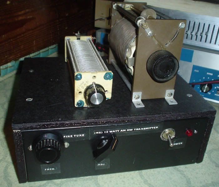
Complete unit with roller inductor and tuning capacitor sitting on top... (note: you can't see the freq. adjust because the fine tune knob covers it in the pic)
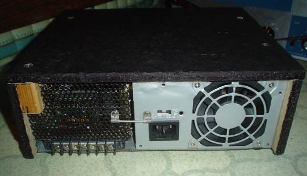
Back of unit, note the PC power supply back which I used as part of the back covering
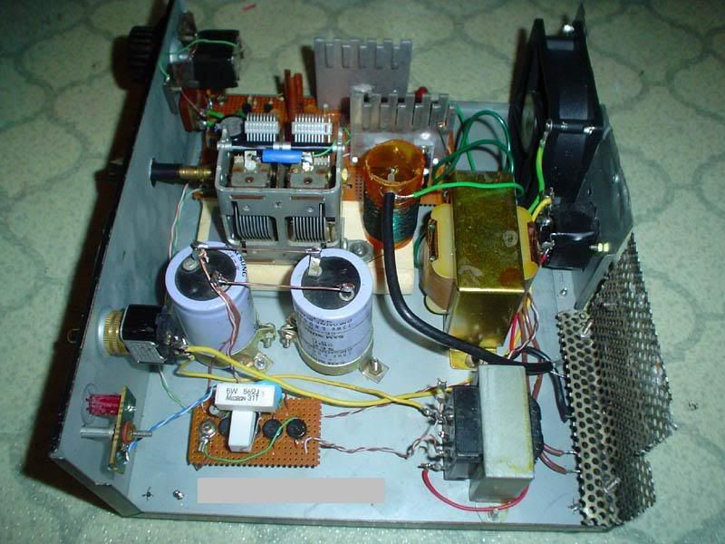
Inside guts, power supply at bottom of pic and transmitter at top. C3 coupling capacitor and coil seen in center. Small transformer is 3amp 24 volt, larger transformer is used for modulator not shown in pic...
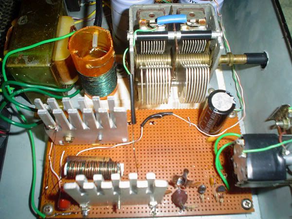
Closeup of some of the RF circuits, some parts are hidden behind heat sinks but you get the idea..
Hey Darklife... this looks awesome. Could it be built using other types of mosfets such as computer power supply ones, or different model ones?
Sure can Most power mosfets will work down on the AM broadcast range. Most people seem to use the IRF type mosfets like IRF5xx. My previous transmitter used a mosfet from a computer power supply. It was a small 400 volt one and I drove it on 24 volts w/o any problem at 1610KHz. It's when you get into higher frequencies that enhanced power mosfets show their true colors as to their upper frequency handling and efficancy.
This is My transmitter I use on 48 mtr 6306 kHz. It gives 15 watt carrier. 60 Watt PEP. ;D It was this transmitter i used for hopping over the ocean from Europe to the USA. Received By Courious George & Dave Valco.
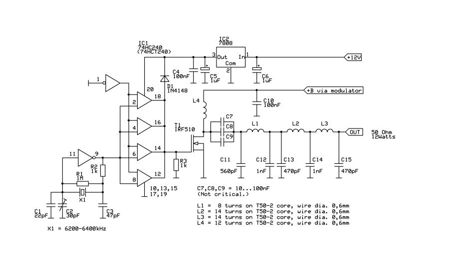
And this is the schematic of it ..
Changing the X-Tal and the lowpass filter you can use it also on AM 1600+ ore in the 76 mtr 3900 khz. ;D
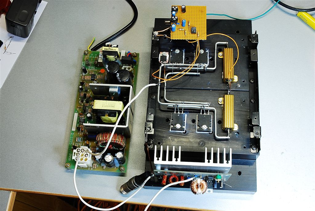
This picture below is my 76 mtr version 3932 khz with series modulator and switched power supply( 26 V DC ). Transmitter is mounted on the lowerside of the series modulator.
How are you getting 60W PEP from an IRF 510 single ended without killing it? I could only do similar with a push-pull output.
Peace!
I was kind of wondering the same thing. Most of the grenade type transmitters using IRF510 get around 2.5-5 watts carrier, 10-20 watts with full modulation. I'll have to look at the IRF510 specs again just out of curiousity . Anywho thanks for the pics MRF, always fun to see homebrew.
How are you getting 60W PEP from an IRF 510 single ended without killing it? I could only do similar with a push-pull output.
Peace!
Most people drive the IRF sine wave , but i drive it with the 74HC240 and that is almost square wave. So the IRF is switching fast from close to open in a 50 percent dutycycle and thats the Trick. The Fet is working like a switch and when you do it right the Fet is not heating up so strong than when you drive it sinewave. ;D
Make it in this way and try it. On the picture you cannot see the IRF510 and the bandpass filter capacitors becouse the are under the PCB. For filtering capacitors i use ATC`s.
MRF.
I drove mine with a 50% duty square too with risetimes in the tens-of nanosecond range with up to 12V p-p drive. 5W power out at best.
It seems an equal amount of people have luck as those who cannot duplicate these results. This makes for a fine mystery to persue.
I drove mine with a 50% duty square too with risetimes in the tens-of nanosecond range with up to 12V p-p drive. 5W power out at best.
It seems an equal amount of people have luck as those who cannot duplicate these results. This makes for a fine mystery to persue.
Peace!
I think dat you mismatch the IRF510 to the lowpass filter and antenne. At this time i have 2 transmitters working the same way on diffrent frequencies both giving > 14 Watt carrier on 12 volt.
The match i made was done with RFSIM99 & filtering also. The impedance of the IRF is around 10 ohm on 12 volt so you have to match it to 50 ohm correctley and than lead it trough the 5 pole Chebyshev filter.
In Holland i think there are about 25 transmitters working this princiepe all with same results.
I think dat you mismatch the IRF510 to the lowpass filter and antenne.
Now THAT is entirely possible.
I am primarily a valve tinkerer and output matching transistors is a new area for me.
The impedance of the IRF is around 10 ohm on 12 volt....
My math comes to the same conclusion.
I plan on revisiting this using a tuned tank and output loop, which I am far more familiar with.
Initial trials at this power level was PP with a toroidal impedance transformer. Transistors were cool enough they did not need a heatsink, but for some reason the power was being gobbled in the toroid core itself and was heating up dramatically.
In Holland i think there are about 25 transmitters working this princiepe all with same results.
When you want I can give you the match and filter disign all tested for 1620 kHz , 3920 kHz & 6300 kHz.
Make this transmitter above and you will see it is working FB ! One notice keep in mind. First switch on the X-Tal part with the 74HC240 when you hear the carrier on the RX than switch on the final. ( dont forget and do it this way otherwise you kill the IRF510 ) The 74HC240 can only drive the IRF510 !!!! others have to mutch gate capacity.
When you want I can give you the match and filter disign all tested for 1620 kHz , 3920 kHz & 6300 kHz.
Thanks for the offer!
Those frequencies are very much used here on the Canadian west coast. My target frequency is in the 60M band. I can use the ARRL tables to derive a filter
One notice keep in mind. First switch on the X-Tal part with the 74HC240 when you hear the carrier on the RX than switch on the final. ( dont forget and do it this way otherwise you kill the IRF510 )
I was just thinking this on my bench last night, "What if the oscillator konks....?"
I will design failsafe that if the osc konks out, the output will land on logic "L" instead of "H". This is easy enough done since I don't have an exact 60M crystal I want to use, but have now made an analog osc with doubler. Then that will go into a schmidt trigger, then to the 74HCT. I just chose input gate pulldown or pullup as needed if the osc fails, the IRF510 gate lands on LOW
The 74HC240 can only drive the IRF510 !!!! others have to mutch gate capacity.
I just see my failure in this.... I have been using Japanese MOSFETS from SMPS (because they are a dime a dozen... hey, I'm Dutch ;D ) and compensating the high gate capacitance by resonating it with an inductor.
I need to order the 74HCT240 (I read the HCT drives at RF better than the HC, what is your experience?) and schmidt anyway, I will add some IRF510's to the list.


 . Coupling capacitor C3 was put on a wood block to isolate the body of it from the ground.
 It sure sounds great on air
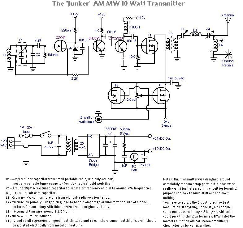
 ~~~~~~~~~~~~~~~~~~~~~~~~~~~~~
 ~~~~~~~~~~~~~~~~~~~~~~~~~~~~~