Those frequencies are very much used here on the Canadian west coast. My target frequency is in the 60M band. I can use the ARRL tables to derive a filter
Give me your frequency than i will calculate the filter for you.!!!
I was just thinking this on my bench last night, "What if the oscillator konks....?"
I will design failsafe that if the osc konks out, the output will land on logic "L" instead of "H". This is easy enough done since I don't have an exact 60M crystal I want to use, but have now made an analog osc with doubler. Then that will go into a schmidt trigger, then to the 74HCT. I just chose input gate pulldown or pullup as needed if the osc fails, the IRF510 gate lands on LOW
I did the same in later experiments... ;D
The 74HC240 can only drive the IRF510 !!!! others have to mutch gate capacity.
I just see my failure in this.... I have been using Japanese MOSFETS from SMPS (because they are a dime a dozen... hey, I'm Dutch ;D ) and compensating the high gate capacitance by resonating it with an inductor.
I need to order the 74HCT240 (I read the HCT drives at RF better than the HC, what is your experience?) and schmidt anyway, I will add some IRF510's to the list.
Peace![/quote]
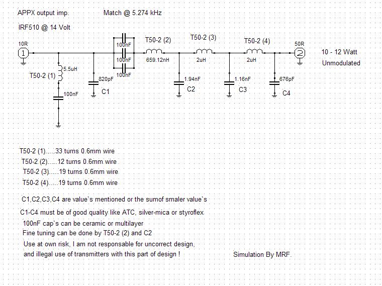
I`m using from Phillips the 74HC240N . & don`t forget the T50-2 cores.
I can give you the layout of mij TX PCB when you want.
It is a .LAY extension so you can only open it with Sprint5
Let me know your E-mail adres than i will send it to you.
Mine is the 3 letters from my nick name followd by radio@hotmail.com
That's a whitepaper on doublers I haven't seen before. Will come in handy
I did explore several variants before deciding on transistors for efficiency. BUT, while the transistors are efficient, they aren't as clean as diodes. The tuned circuit cleaned that up though.
(as a crossover designer, I even have non-inductive film caps [tested to 10MHz] with kooky values like that ;D )
The values are not so critical +/_ 5% is good enough assemble them with smaler ones. With the coils on the terroids you can make fine tunning. Take capacitors such as FKP types high voltage , they can do the job.
I have been experimenting with this for the last three days and can not get 10 watts clean and steady out of one IRF510.
The best stable class-E carrier is 2.2 watts with values and schematic shown. 6V p-p drive from a 74HC240 to the gate just can't turn it on far enough. Nice clean squarewave. I am using 13.5V Vdd.
I made a level translator to drive the gate with a solid 12V squarewave (13.5V Vcc - Vce(sat)) and was able to get around 10 watts, but was so unstable that once balanced, if a flea farted on the drain capacitor, it would break into a white noise generator and knock out the FM radio. Never mind trying to modulate that!
The best luck I did have was with a K2350 Japanese MOSFET - a little harder to drive because of the bigger gate, but could make a 5 watt class-E carrier that was stable even with coffee spilled on it when running (heh, don't ask )
Best luck with IRF510 was losing the class-E drive and just transformer coupling and driving standard class-C.. it'll give clean, stable output power as hard as you drive it. Last test of the night I had 15V p-p hitting the gate, 5W out, 55% efficient, but stable. Earlier test was 25V p-p into the gate, still 5W out, but 79% efficient.
What I have learned: - That capacitor from drain to ground !!!CRITICAL!!! If you get one thing right and bugger everything else, just get that dang cap right! If you have a 470p mica compression trimmer, use it. - MOSFETS with teeny gate capacitances love to make VHF parasitics - use 5t #24 on a 5/16" drillbit chokes EVERYWHERE except the source lead. - Gate drive... slam it hard! Think rail-to-rail and with as low impedance as possible. No, fancy driver IC's aren't needed. The 74HC240 does make life easy, but a pair of 2N2222 voltage amps to square things up, then a 2N2222/2N2907 class-B complimentary pair do the same job and don't care about static, 5, 6 or 15V supplies. - A MRF510 at 24V solid to test "100% modulation" will thermally overload in very short order. Even with adequate heatsinking and at 79% efficiency, the thermal resistance of the die-to-case can't take even a short period of time at 20W out with 24V solid. It is definately an ICAS device, not a CCS one. - Output tank tuning is much less critical. MOSFET's are more forgiving here than their bipolar cousins. Using tunable coils and caps, ended up with optimum values that were nowhere near any transistor output impedance formula. Neither the R=E/I discussed here, or the Class-E website of R=(E/I)*.57 or the ARRL's R=Vcc^2/(2*Po). The tube guys had it right with adjustible everything here too
I belive your transmitter may be an "Angel's Balance". Perhaps the IRF510's sold by Digikey are weired, but I can not duplicate this transmitter as class-E with that transistor.
OK, here's a trick people that you won't find on any "Grenade" board or schematic - IRL510, NOT IRF510 (both from International Rectifier). The gate of a "L" is for logic level.
Also, a groundplane (double sided PCB or "dead-bug" style) is absolutely essential. Perfboards need not apply.
You will then most likely make this work
But put it on a spectrum analyser - any mod peak above 12 to 15W will have parasitics I cannot get out.
Secondly - unless you have 10+ years in DIY'ing, do NOT even THINK of trying this project (I mean the one MRF and I are on).
Post by centrepoint on Feb 24, 2009 7:21:02 GMT -6
I've been playing with this design too. Driving an IRF510 at 13 MHz, I still got over 10 Watts carrier. If you use the unused gates (ie those tied to ground) as well you can get even more 'umph' on drive.
At 7 MHz using all the gates you can drive an IRF520 to about 20 Watts carrier. At 4 MHz you can use the circuit as it is to drive an IRF520 to 20 Watts + carrier (with the right output matching).
The 'what if the oscillator konks out' problem can be solved by putting a 1K resistor from the IRF gate to ground as well as a 1N4148 (or similar) with the cathode (pointy end) to the gate and the anode to ground. Then insert something like a 10n to 100n capacitor in series with the output of the 74HC240. Now if the osc fails, the IRF gate voltage will sit at zero.
I've also put a 10 Ohm resistor in series with the gate input with about 8 turns of fine wire wound around it. The resistor stops the IRF from oscillating at VHF and the coil helps tune out the gate capacitance.
All in all, a very simple design that works extremely well.
If you're getting less than 10 Watts carrier with an IRF510 either:
* Your output matching network is wrong, or * There is too great a voltage drop across your modulation transformer
Remember that to produce even 10 Watts carrier, you're drawing about an Amp at 12 Volts. If the DC resistance of your modulation transformer is, for example, 3 Ohms, you will therefore be losing 3 Volts into the IRF. At 20 Watts (and hence 2 Amps) it gets worse still!
I've seen various figures quoted for the power of the modulation amplifier needed - does anyone have any thoughts? For a 10 Watt transmitter, which peaks at 40 Watts on full mod, does the audio amp need to provide those 30 Watts of additional power?
Just curious if anyone knows the upper limit frequency on the IRF mosfets. If you got it running on 13MHz then I wonder how well it would work at 15 or 17MHz?
I have been toying with the idea of running a transmitter at 17MHz for fun since a dipole at that frequency would be small enough to be easy to setup at my location.
Freq. Generated by programmable Cypress blueberry board into a fet driver , the final is an IRF510. it gives 13Watt carrier 52Watts PeP. @ 6.310kHz
Greetz MRF.
Wow so simple and clean looking! Those programmable frequency generators are really becoming popular. I may have to get one for myself in the near future.


 )
)


 ~~~~~~~~~~~~~~~~~~~~~~~~~~~~~
 ~~~~~~~~~~~~~~~~~~~~~~~~~~~~~
