Hey, I am messing around with building the "junker" AM MW 10 Watt Transmitter from the schematic by Ken (Darklife). This stuff is pretty cool man. I have a couple of questions though if I could pleases get some help that'd be MUCH appreciated. First, how I can tell to what frequency I have it tuned? Second At the top of the schematic in the middle under ’10 Watt’ title there is a resistor that connects to a C +12V. That resistor isn’t labeled; what rating that resistor should be? Thanks soooo much for the help in advance!!!! I can't wait to get this done, I'm having fun if you can't tell already.
Hey, I am messing around with building the "junker" AM MW 10 Watt Transmitter from the schematic by Ken (Darklife). This stuff is pretty cool man. I have a couple of questions though if I could pleases get some help that'd be MUCH appreciated. First, how I can tell to what frequency I have it tuned? Second At the top of the schematic in the middle under ’10 Watt’ title there is a resistor that connects to a C +12V. That resistor isn’t labeled; what rating that resistor should be? Thanks soooo much for the help in advance!!!! I can't wait to get this done, I'm having fun if you can't tell already.
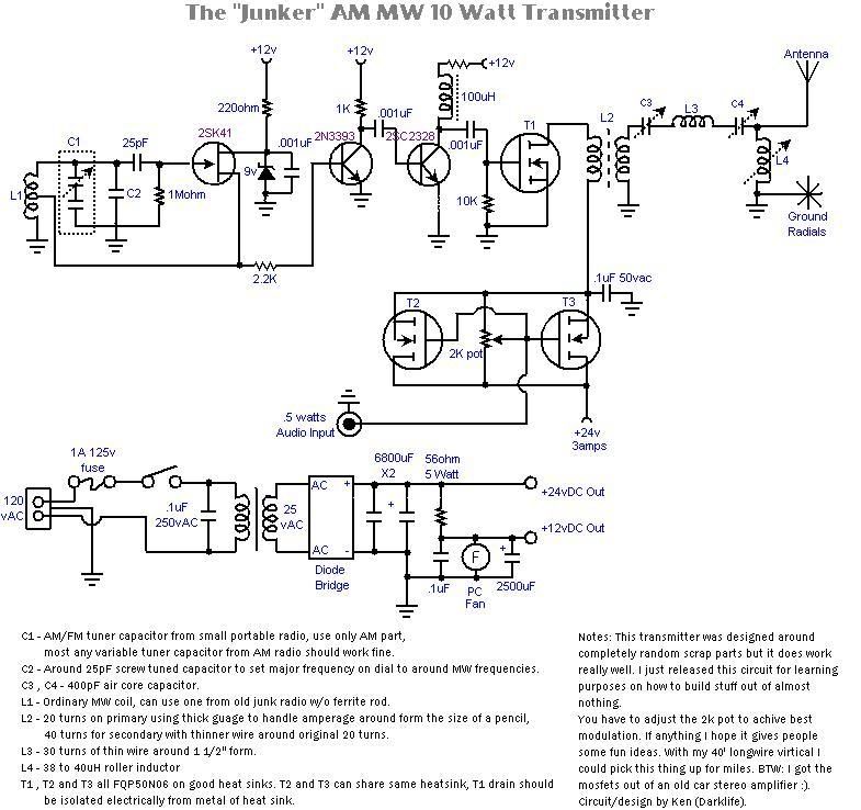
I really don't remember the value of that resistor and I forgot to put the value in the picture for some odd reason. My guess is that it was 10ohm. The MW coil was just a random coil I scrapped from a small AM radio, the kind that is in those shielded boxes with the screw adjuster. You could probably even use a ferrite rod with a prewound coil. To test what frequency it's working you should get a hold of a frequency counter, or just tune around on your radio until you find the carrier and adjust the oscillator from there. As with most transmitter circuits, build the oscillator first and make sure it's working, then their buffer stages, then at the end build the PA section.
I come to seek assistance again from the great knowledgeable Transmitter King. I have been quite busy with work, tons of hours going on right now between work and home life, etc. and I think I am screwing a thing or two up along the way during the moments I can steal away for my radio building projects. I am really enjoying it but am getting a bit frustrated as things aren't working out 100% with me just looking at the pics and schematics. I was wondering if I could talk you into building a fully functional model of your "Chug AM" transmitter and send it to me as a template of sorts. I am much better able to grasp the ins and outs of construction when I can hold a completed model in my hands, see it in 3-D exactly how it should be laid out and put together. A bit of a hands on learner as it were. I would ofcourse be very willing to pay you for it, and pay for the shipping. Could I please twist your arm into assisting me in this manner? If so How much would your creation cost me and what would be an approximate timeline for completion and shipment? I thank you much in advance for your help Mr. Michaels. As I've said before, you are the man.
Yeah sorry but I'm not selling the Chug AM transmitter. The design was built out of mostly random parts, though the schematic for it could be replicated using off the shelf parts if you're knowledgeable on electronics RF design.
I did get your email but I felt like responding here to also let others know I will not be selling homemade stuff that I built in this way. Also I believe the laws here do not allow for me to sell an uninspected transmitter, especially one used on broadcast bands weather it be for legal or non-legal purposes. I think if it were in kit design it could be sold though, but I don't have the resources right now to fabricate transmitter kits to sell to people. Maybe sometime in the future.
Your best bet is to learn enough from articles here and other places and design your own.
Moved these posts to its own thread. Trying to keep the Schematics thread clean of off topic, or side topic posts.
The "unknown" resistor off the 12v buss is what they call a current surge absorbing resistor. Usually 10 ohms in value and wattage is dependent upon total current load in the circuit. In this case, probably a 1 watt will do just fine.
In some of the early solid state televisions which were powered by switching power supplies had current surge absorbing resistors put inline with the 120vac input before the power supply. These were 20 watt resistors in the cement package and were usually around .3 to .5 ohms.
Their purpose is to allow for "soft" turn on and absorb any fluctuations in the voltage supply which may overcome the limits of the components. The resistor would absorb these spikes, or if the spike was large enough, go open and hopefully open before any spike enters the supplies and damages components. Usually the inline fuse would also blow in these cases, that is if the manufacturer installed fast blow fuses..which 9 times out of 10 they were not and the set would end up with blown components in the power supplies.
But when people want cheap...that's exactly what they get.
Peace!
K-ROCKS RadioOne
ZeroPointRadio
AM Stereo 1670
FM Stereo 92.1
How can I build this but in say a 50-100+ watt model?
You should take a look at the Class E website to get some ideas... www.classeradio.com/
The way I based the transmitter that is depicted in this thread works the MOSFET much like a class A amplifier in that as long as it's receiving a steady oscillating voltage it will be self biased somewhere near the halfway point allowing the negative and positive cycle of the sinewave to be amplified. This is very linear which is great in that it generates little harmonics and is clean as long as the oscillator signal is clean (which mine was). Problem is that it's highly inefficient to run a MOSFET in a linear way compared to as a simple on/off fast speed switch. That is where Class D and E come in, they run a square wave to the MOSFET making it act much like a fast switch. The square output then being filtered to make a clean sinewave at the antenna.
I mention all of this because my design did work, and did provide 2.5 to 5 watts carrier (10 to 16 or so watts modulated) but it created a lot of heat and I needed a really large heatsink and fan.
If you are going to be using MOSFETs as a simple transmitter I would highly suggest using Class D/E instead. You can get a lot more power out with less heat using that method.
Since you're looking at 50-100 watts of power the only practical way to do that is using Class D or E because of the limitations of running any MOSFET in a linear way just isn't practical at those power levels. Also keep in mind 100 watts carrier power needs at least 400 watts for modulation headroom. There is where the fun comes in!
People forget how much power 100 watts is on AM. With MOSFETs pushing that kind of power you are going to need one high wattage power supply that can handle the current. Tubes may be another good option at those power levels.
The picture section gives you some idea what kind of work is involved in building something like this. A 50-100 watt transmitter wouldn't be that much smaller or easier to build. Generally it's easy to make a few tens of watts, but once you start getting into those double digits things get real hairy.
That is perfict. I knew a few people that sell class e rigs for 80m and are very nice with there own pwm power supply. Its that I want to be heard and not worry about lugging my johnson valiant and generator with me.. thanks for the info. I was also thinking of moding a 40m ham amp and reworking the filtering and using somthing smaller to drive the amp.. that is the other opition I am looking at.


 ~~~~~~~~~~~~~~~~~~~~~~~~~~~~~
 ~~~~~~~~~~~~~~~~~~~~~~~~~~~~~