I have been debating if I want to build a new MW or SW transmitter. I was on 1610KHz for the longest time with 50 watts until my home built rig fried from the RF output coil overheating and shorting out causing the pa transistor to explode.
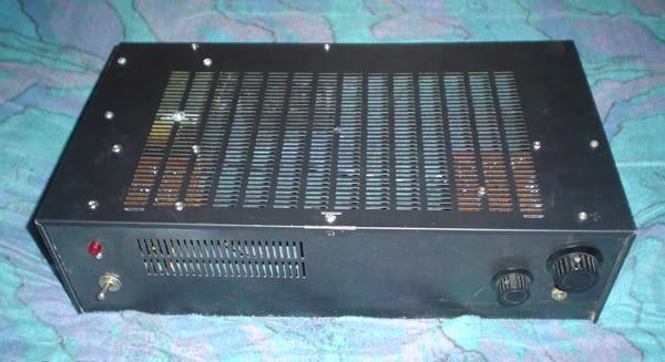
Well I wanted my next project to be built like a tank so nothing stupid happens like that again. Got the power supply and chassy built but because of lack of listeners on MW and my antenna not being good enough for such low frequencies I now decided to build this one for SW.
So far so good. Got the VFO working and getting about a watt out of three transistors w/o problem so now it's just soldering time and next working on a mod/pa.
I have no idea what to expect though with broadcasting on SW. I have a bad feeling the feds probably monitor shortwave a lot more then the other broadcast bands right? Another thing is that I don't know anyone who even owns shortwave radios besides myself besides a few hams in the past who I rather not want tuning in if you know what I mean .
Well it will be interesting and fun. If all goes well you may be catching me doing a show or two on 6925KHz.
Anything you guys think I should be warned about or tips before I go head first into this?
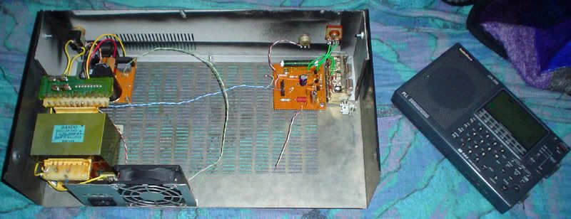
Well I got the basics built so far. I made the chassy and power supply. The 1 watt signal generator is now built and tunable from 5-9MHz and I now have it soldered together on breadboard and built into my own home built scraps...
That image shows the thing so far. In the future there will be a meter for RF and other dials and shit. But for now this is all I have got built so far...
I designed the second buffer amplifier so that I can vary the voltage to it to allow me to choose how much output power I want to use. So far the unit produces a nice clean sign wave at 5-9MHz with variable power output from 0-1 watts.
Next major thing is building the power amplifier and modulator, you know the fun part!
I will keep this updated as I continue this project. This is my first shortwave transmitter I built that is this powerful for this purpose. All junk box parts, all junk paper ideas. It's going to be fun .
I should tell you all that old chassies from stereos and stuff makes great things to build into. I just scrap up old stereo receivers and keep the shells, makes nice project boxes as you can see.
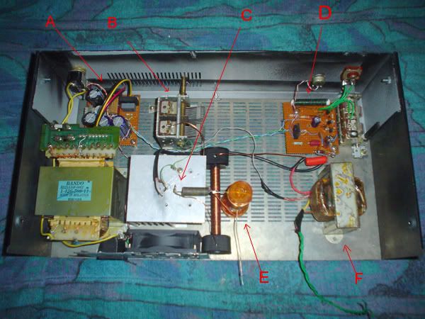
Okay from A-F: A: This is the simpleton powersupply. Gives 24 volts to the osc/buff board and 24-90 volts to the PA/modulator stage depending on what I plan to build for a PA next. B: Simple RF output tank. Nothing more then an MW varycap with a 15 turn coil in serial with output. C: That is were the PA transistor belongs. I have tried a few mosfets but they give out for some reason. I know that you need to figure double the vcc voltage on the drain because of the flyback effect of the output coil and add in the modulation voltage but even then my mosfets died off when tuning the load and tune varicaps. I will figure it out though D: The simple 3-9MHz signal generator. Works perfect w/o any strong harmonics or hum. By itself it makes a damn nice sign wave signal. The variable resistor next to the red line is for RF output level, varies from 100mw to 1watt output to the PA stages. E: simple output network. Standard cap,coil,cap network. I plan to add a vary cap on the tune part of the filter but right now the load vary cap is more important to my antenna type. F: If you haven't guessed already why are you reading this? It's the modulation transformer. Once I get the PA figured out I plan on experimenting with both high level modulation and heising modulation to see what sounds better and gives a higher modulation percent.
So there you have it. This is my complete junk box rig so far. It is a total peice of crap but I am sure as long as my scope says it is giving a good signal, it must be good .
All I need is that PA transistor yet, As you can see the PA isn't built quite yet.
Just a few funny notes: The coil on the output network is wound around a pill bottle. The power supply came from an old RCA surround sound amp that was blown. Modulation transformer came from an old theater amplifier, fan from computer power supply, the standoffs that hold the RF choke for the PA are actually bottle caps from Brandy alcohol bottles, metal case from old stereo, front panel from another old stereo cut to size. Most all the parts are total scraps and just plain junk. But don't worry, I don't put out a signal unless it matches the best . Enjoy.
Howdy! Looks like an interesting project; I hope to read more about it. Would you consider publishingor linking to schematics as you go along? I'd sure like to know more about that little VFO :-) Thanks!
Actually I scrapped the project in favor of using the parts on a MW transmitter. The VFO was a simple hartley oscillator based on a FET for stability. Something kind of like this first schematic here.. www.pan-tex.net/usr/r/receivers/vfo.htm
I will probably hit the workbench soon again and design a small compact 10 watt or so SW transmitter that covers 5-9MHz with VFO if I get the parts I need.
VFOs aren't as bad as people make them out to be, they can be made really stable if designed correctly. It sure is easier then buying crystals for whatever new frequency comes to mind


 .
. ~~~~~~~~~~~~~~~~~~~~~~~~~~~~~
 ~~~~~~~~~~~~~~~~~~~~~~~~~~~~~