After playing around with the old BA1404 based FM Ramsey transmitter again I forgot how nasty those high frequencies can sound on a cheap transmitter. Figured I would whip together a 6 pole 15kHz low pass filter. I did this with 3 JRC 4558 8 pin opamps on a perfboard and was amazed at the results. Not the sharpest cutoff ever but it protected the 19kHz pilot a lot more than without, and really cleaned up the 38kHz stereo subchannel.
I had one of those ah-hah moments realizing just how important it is to filter the audio that goes into these smaller FM transmitters. I'm sure an 8 pole filter would have even been better and there is no reason I can't add another chip to do just that. I only have so many opamps laying in my part box though, so I plan on using another one to notch out anything at 19kHz to completely protect the pilot.
I will post schematics soon when I get it all put together. The question is banging around in my head though how many other pirates here use a quality audio filter ahead of their FM transmitters input? What kind at that? Without the filter I'd imagine audio would sound awful on those chinese transmitters, MP3 transmitters, and most kits like the Ramsey FM10.
If you ever wonder how good your transmitter sounds there is a quick way to do it, just plug in a sine/square wave generator and sweep the thing from 10hz to 100kHz. There is software to generate those waveforms for you if you don't have the real deal. Do so with either the left/right or both channels and listen to your audio output on a good radio. El-Cheapo transmitters will have nasty harmonics when getting above 8-10kHz audio, and will even let things above 15kHz get into the audio even allowing audio to get into your stereo pilot and stereo subchannel! Squarewaves are the real test. If you're going to hear harmonics or aliasing this type of waveform will bring out the beast. A quality transmitter and/or audio processor will not have those issues and will not pass anything above 15kHz (especially harmonic content in music, like that produced by kick drums and cymbal crashes).
When I swept the Ramsey FM10 with a square wave the sounds I heard on air were sickening. Most frequencies killed the pilot even with very low modulation, made odd synthesized sounds pop out, multiple tones that didn't even exist, and stuff that sounded like it came from a horror movie. After running through the 6 pole filter? Almost flawless like a pro transmitter, nice clean square wave sound w/o distorting the audio.
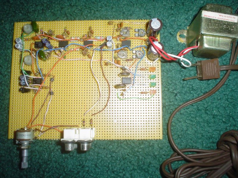
Well this is what I built so far. Simple (in theory, but trust me it wasn't the most fun thing I ever made) 6 pole 15kHz low pass audio filter and 19kHz notch filter times two for stereo. Took me 3 hours tonight to solder the design I had on a breadboard onto a perfboard. Got it all together and tested it on the scope and got absolutely nothing. Duh, forgot to solder the V- of the first opamp lol. Fired it up and worked wonderful. I peaked both channels to notch out anything at 19kHz. Just used a simple signal generator and tuned up the pots. There is such a deep null that I don't think it's possible for anything to kill the stereo pilot now.
The 6 pole filtering seems like enough. I can still hear some aliasing when I force higher than 15kHz audio through it into the transmitter, but it's so subtle that I figure this is on par with quality broadcast equipment standards.
Taking a sine/square audio generator to it was the final proof. At close to full modulation both sounded great with little to no harmonic content. Trying it without the filter and OMG! It's like feeding the transmitter with everything but the audio you want.
This experiment proved to me, and was a lesson in how FM broadcasting is not simple games. When running a transmitter on FM with no front end audio filtering you end up with harmonics from audio beating against 19kHz stereo pilot tone, aliasing from the 38kHz stereo sub-channel, multiple harmonics up the audio bandwidth causing tuners to mistakenly kick in RDS or other features that aren't even there, and can even broaden the bandwidth your transmitter uses which ultimately does two harmful things... It causes interference to adjacent stations, and lowers your listening range because more bandwidth = less range, especially if you are tossing a lot of garbage into high frequency audio above the human hearing range than needed when modulating and transmitting that information!
The old rule still stands, mono will get a signal out farther than stereo because of less high frequency content (pilot+L-R channel) in the modulated index. That same rule works for unintended garbage above your audio range like that caused by cheap CD players and computer sound cards. So if you're putting out audio harmonics (well above the human hearing range) and after my tests I will bet most cheap transmitters and mixer boards feeding them are, you will be consuming more bandwidth along with reducing your signals strength.
The lesson I learned? Not only is an antenna filter important for obvious reasons, but so is a proper audio filter to brick wall anything above 15kHz.
It seems silly to me now but for a long time FM pirates were only worried about harmonics caused by their transmitted frequency. Few of us worried about issues caused from the audio itself which if improperly setup can cause enough interference on it's own, along with degrading ones signal they worked so hard to put up.
True in today's car audio world where fidelity no longer matters people probably won't notice a quality FM signal from a tin can. Don't let that be an excuse though.
EDIT August 15, 2020: Re-uploaded images after tinypic went offline permanently. Feel free to let me know of other broken image links.
The Ramsey FM 100 and 100B models and the transmitter companion have switched capacitor filters that run off the microprocessor clock. Those work incredibly well and can be adapted for any transmitter by building those circuits.
Can you provide a scan of that schematic, the photo is a bit hard to see some of the part values. (old age or too much dust on my monitor!)
Peace!
K-ROCKS RadioOne
ZeroPointRadio
AM Stereo 1670
FM Stereo 92.1
I will post the schematic once I get it drawn up in Dia software. Would be interesting to see the schematics of those ramsey transmitters and how their filter works. I know there aren't any schematics on the web that I have seen using that sort of method you describe.
Still don't have the schematic drawn yet but a (long winded) note on progress... I added a soft clipping diode circuit to the schematic which should never kick in unless the compressor overshoots on sudden loud volume.
That brings me to my second updated part: I added a single opamp and JFET transistor stage for compression (before the filtering) which can compress and handle things within 60db of audio range! That alone should make a huge difference. With a few variable input pots it will allow one to control compression from just plain limiting to an amount of compression that is ridiculous. Of course finding the sweet spot is the idea, and then adjusting the clipper pots so that any overshoots are completely clipped to protect the integrity of the FM carrier signal.
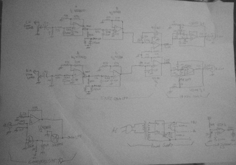
So, the project so far has become a compressor > clipper > 6 pole 15kHz filter > 19kHz notch filter, in order. All using low noise JRC 4558D or DD generic audio opamps for a total of 5 chips. I am sure any OP Amp would work, but using low noise ones are obviously best.
It sounds complicated, but really the complexity in the circuit comes from having to make two of them for stereo!
When I get done with this my guess is that it will rival the Ramsey STC kit. It does everything that kit does minus 2 poles of low pass filtering, which I find is unnecessary anyways since the more filtering the less it has effect after a point, and naturally the 19kHz pilot filter almost acts like another 2 pole LPF by itself. Then to add in the simple compressor really sets it above the rest!
Soon to release schematic and plans. This project could and should be a definite build for pirate FM broadcasters. It cleans up the signal so much it seems insane not to use it or something similar.
What amazes me at this moment is after testing what has been designed so far. No matter what material is played through the transmitter it sounds clean. No matter how loud or distorted the audio the stereo pilot is constant and unaffected. No matter what frequency and how much distortion I can not hear it effect the L-R sub-stereo channel.
In other words, the audio sounds and looks clean on the transmitters output no matter what I feed it. The integrity of the signal is preserved to the point that it's almost unaffected compared to a silent signal.
;D
A side note (up until this project), I have been using an old superscope cd-310 cassette deck that I ripped the cassette guts out of years ago and used its built in recording audio limiter. I forced it into record mode and used its in/outs for compression for FM broadcast. Also these cassette decks had a built in 19kHz filter because many people plugged them into stereo receivers to record FM broadcasts to listen later, and the pilot of yesteryear receivers weren't filtered well, so to record to tape the cassette manufactures had to include a 19kHz filter! Don't know if anyone here knew this, but old cassette decks with built in mic/linein compression CAN BE USED as primitive audio processors for FM broadcasting for that very reason I still feel bad about gutting the cassette components just to turn it into a device for this purpose, though it worked well for years, it later angered me that I ruined a HIFI piece of stereo gear when I grew to appreciate older HIFI stereo gear.
Decided to go all out and build in a simple FET+OPAMP stereo compressor on the input. Remarkable how simple it was to build a stereo compressor with little to no distortion. Also added a few LEDs to show +8.5 and -8.5 volts on the chips which is what I designed the supply to use, and two green LEDs to show soft clipping which is ahead of the filter.
Here is the perfboard so far...
Soldering work..
and the schematic as drawn quickly. I will write up an official schematic when I get the motivation to draw it up using software so it doesn't look so bad (very soon)...
So this audio processor so far is a brick wall audio limiter (or compressor depending on how much audio you feed it), a low pass 15kHz filter, which after the second pole contains an audio clipper to catch any overshoots in the compression/limiting, then 4 more poles of filtering of <15kHz with a slight gain (ring) at the peak point of 15 kHz. Then it finally passes a 19kHz notch filter to protect the stereo pilot signal and reduce aliasing greatly.
I learned a few things about FM broadcast processing while building this. Audio Clipping is actually a beneficial audio effect when applied properly. Obviously at low frequencies it will cause distortion to the human ear, but when you get above to the high frequencies the human ear doesn't have the ability to so easily recognize clipping distortion, and also the filtering after the clipper rounds those square waves all off anyways. So what does that mean? It means you can make much more compact sounding audio. No the goal isn't a wall of sound like some radio stations, I do enjoy dynamics as much as the next person. What it does mean is fitting in more audio into the baseband, and reducing harmonics which cause the FM stereo signal to become wider causing adjacent interference to stations next to them. It also does a major important thing and that is compact the audio to a level that when modulated reduces modulation deviation while increasing modulating density and as we all know <bandwidth = more signal coverage.
This has been a damn interesting project. With AM it's about loudness so to fight distant static, with FM we don't have that problem as either someone picks up FM broadcast or doesn't, there is little play in between. Radio station engineers have been wrong for assuming a louder FM signal is better. In reality it only reduces long distant static, but at the expense of audio fidelity, dynamics, and ear fatigue.
I learned that a lot of classical music stations use an audio processor which is almost identical to mine. They use an Orban 8000 which was the first audio processor made by Orban, and is still well known and appreciated and there is a reason why.. The sound that goes in is the same sound that comes out.
Sounds crazy, but proper audio processors shouldn't add their own character at all unless the audio needs it. Most modern day audio processors do nothing when working with modern day music, the reason why is simple, it doesn't need to do the job twice.
A good audio processor doesn't change dynamics much. This got me to thinking about modern day radio stations and the idiocy that surrounds FMers using compression to the point of total ear bleeding. What's interesting is how this is not even necessary with FM at all.
So LONGGGGGG post, but I just figured I would drop my knowledge I gained while working on this. I learned that FM processing is just as important as the FM transmission gear. I also learned that FM processing can actually be MORE complicated. Anyone can put a signal into a frequency modulated oscillator and end up with an FM bug, but real broadcasting requires a great deal of understanding of the techniques of processing (filtering, clipping, limiting, compression, more limiting and clipping, more low pass filters, 19kHz pilot filter, band notch filter for L-R channel, so on and on).
After studying this stuff it makes me wonder how those silly IPod transmitters work at all w/o causing awful audio.... oh wait they do!
BTW that empty space in the center of the perfboard I am considering adding another audio limiter, but one that only works on high pitch audio.
One thing that sucks about butterworth filters is that when running a square wave into them after the frequency they filter they tend to have boosted junk that makes the whole bandwidth of audio flat up until that point.
With FM transmitters it is important to never overmodulate because when one does it causes all sorts of audio problems, interference and junk to appear as sidebands which leaks into stations next to you. It's no different than CB radio operators using linear amplifiers w/o having a clue how to drive them. They end up causing damage to every channel next to the one they use.
When hard clipping audio you will reduce over-modulation directly, however introduce a new problem and that is harmonics in the audio. Take any square wave and clip it compared to a sine. You will end up with more energy with the square. With modern day electronic music there is a lot of square wave synth type sounds.
So peak limiting the high frequencies help that I think. Run another compressor before the limiter in the processor. That compressor only working on high frequencies. Thus when one drives the audio with any frequency or harmonic of that it will come out either clipped, limited, or compressed. There should be no overshoot which will make an FM transmitter drop out or cause interference.
Okay time for a few beers and bed. I should be working for Orban, not talking about them lol. Not to toot my own horn, but good God, this shit interests me to no end. Sorry.
Cool deal! One thing to watch for throughout the circuits, as you already noted, are the "sweet spots" for symmetrical clipping...ie not clipping to the point of making waveforms turn into flattops.
Inter-stage AGC or wave shaping circuits may aid in preventing flattop waveforms. Any introduction of a sine wave being chopped at the top will introduce those artifacts your finding above the 19khz wall. Although you may not hear it, the FM transmitter will pass that junk through as well, which you won't hear, but the FM transmitter will see it and that junk will rob both power and bandwidth...not to mention introduce unwanted junk thrown into the baseband which will produce artificial subcarriers of that produced junk.
In other words, if you got junk above 19khz coming out of that project, say 25khz to 40khz of junk, those will show up on the baseband as fragmented subcarriers which will come and go based on the audio coming from the processor. If the junk can't be removed, then you might consider adding a band-pass filter at the final output, totally brick wall anything above 15khz.
Peace!
K-ROCKS RadioOne
ZeroPointRadio
AM Stereo 1670
FM Stereo 92.1
Cool deal! One thing to watch for throughout the circuits, as you already noted, are the "sweet spots" for symmetrical clipping...ie not clipping to the point of making waveforms turn into flattops.
Inter-stage AGC or wave shaping circuits may aid in preventing flattop waveforms. Any introduction of a sine wave being chopped at the top will introduce those artifacts your finding above the 19khz wall. Although you may not hear it, the FM transmitter will pass that junk through as well, which you won't hear, but the FM transmitter will see it and that junk will rob both power and bandwidth...not to mention introduce unwanted junk thrown into the baseband which will produce artificial subcarriers of that produced junk.
In other words, if you got junk above 19khz coming out of that project, say 25khz to 40khz of junk, those will show up on the baseband as fragmented subcarriers which will come and go based on the audio coming from the processor. If the junk can't be removed, then you might consider adding a band-pass filter at the final output, totally brick wall anything above 15khz.
Peace!
After watching the projects output on a software spectrum analyzer waterfall display I was unable to see much happening above 15kHz when frequency sweeping it or playing heavy music. The 19kHz pilot frequency was down in the dirt no matter how loud I pushed audio through it at that frequency or any other. Content above 19kHz was supressed enough that I feel the 6 pole filter is about enough even after light clipping is used near the input. There is some stuff up there but it's minimized to the point where it's almost inaudible when listening for aliasing. Just to be safe I do plan on adding a final filter to the output to make it 8 poles of filtering in total. At this point I am happy with the results as is. Way better sounding than anything I have used so far and does a much better job than any software tool to get the same job done. Thanks for your input. Any further ideas are appreciated greatly.
Simple question: What to do from here with this project before I let her go live on air?
Long thought: I did notice that though the clipping does help it equally has negating effects on audio. It seems when the audio is busy sounding going in that clipping is hardly noticed and really shines in bringing out a nicely compressed sound with no overshoots.
However when playing stuff that is soft with lots of dynamic audio I do notice the clipping on high frequencies. It's subtle but it's there and annoys me no matter how much low pass filtering is added after the clipper stage so I am forced to turn down the internal POTs gain in the circuit before the diode soft clippers.
Seems there is a middle ground on what works for what kind of music goes through the processor. Some styles of music sound undistorted with light clipping, metal sounds undistorted with any amount of clipping, but play some classical and all hell breaks with even light clipping. To make matters more complex, where does one add clipping? The whole baseband or just the high frequencies? Seems I get a different answer depending on who I ask.
I am thinking about just making the circuit ride the gain like a limiter should and ONLY clip when absolutely needed for overshoot of limiting. This would be the audiophile way. People can turn up their volume on soft passages. However there is a sick twisted part of me that wants the audio to sound big like the other guys on the dial.
I guess it's a trade off between a big sound with occasional distortion or a light sound with perfect dynamics audiophile approved.
Maybe somewhere in the middle is sane.
I never realized how crazy audio processing could make a person. After listening to a great number of other stations on the dial it really started appearing to me the subtle differences in their sound. Some stations are outright distorted, others under processed, and then there is the occasional station that does it just right.
I never had the ears to decipher this sort of stuff before until I really payed attention and learning how it works behind the curtain, then it all started becoming apparent to me while scanning various FM stations on a quality receiver. Some station engineers are stuck in the loudness wars mindset, while others finally get it now that it annoys the hell out of listeners. There does seem to be some sort of middle ground where the sound is "radio" like without ruining the original material. I'm just wondering how to achieve that without thousands of dollars of overpriced equipment (designing this current project to be better).
I think this processor is the right start, but it became overly obvious to me how easy it is to go overboard and brick wall dynamics to loudness only to ruin the whole song. Yet too quiet of unprocessed audio rides with the static.
Wow talk about progress so far. Lots of coffee and major reading up on how older analog FM broadcast processors worked I finally got the circuit finalized!
Quite a few things were revamped in the project. The current lineup from input to output is as follows...
Input > Attenuator control > Slow attack/decay baseband audio limiter > 75uS Pre-Emphasis circuit > 6 pole Low Pass audio Filter (LPF) > 19kHz deep Notch Filter > Fast attack/decay HF audio limiter > Audio Clipper > Output
Layout:
The idea behind the circuit is somewhat complex. The input is driven to light compression via the first baseband limiter. This gives quiet passages a bit of a boost but doesn't cause sucking up of background noise.
Next is the pre-emphasis amplifier. This gets the pre-emphasis done before final limiting so that high frequencies can not cause overshoots. This means that the transmitter itself MUST have pre-emphasis disabled or removed. For the Ramsey FM10 transmitter I simply removed the 0.0047 capacitors across the 15k ohm input resistors and replaced them with 0.001 capacitors from the BA1404 chip audio inputs to ground. This successfully removed its built in pre-emphasis.
After the pre-emphasis stage is a 6 pole 15kHz Low Pass Filter. This removes content above 15kHz greatly to reduce interference to the 19kHz pilot signal and the 23 to 53kHz L-R ultrasonic stereo channel.
Then it runs into a 19kHz notch filter. This does two jobs, it removes any audio down to the dirt at the precious 19kHz stereo pilot frequency so that no matter what kind of music is played the pilot remains level so peoples radios don't have blinking stereo lights (switching from mono to stereo rapidly) when playing loud complex music, and it adds additional filtering to anything above 19kHz simulating more poles of low pass filtering above 15kHz.
Finally this all runs into a fast peak limiter to catch sudden blips the first limiter did not. This also sucks up some of the high frequency pre-emphasis sounds and doubles as a second different frequency limiter so it can be assumed the whole project acts like a 2 band compressor in the end. Since high frequencies are greatly enhanced by the previous pre-emphasis circuit, this limiter brings everything to level so not to over-modulate the transmitter.
No compressor/limiter acts perfect on sudden peaks, and even the HF compressor doesn't catch the most sudden peaks in audio (but the physical transmitter and over modulation as a result does!). These peaks are usually so fast that the human ear doesn't detect them much so on the output is an Audio Clipper. This is partially a soft clipper (via the diodes with the 1.6 ohm resistor) with just enough headroom to not distort even when driven hard but still allowing it to clip hard enough to catch anything within <1dB. This allows driving the audio to the floor if wanted with little to no distortion, causing RMS audio levels to reach peak levels thus increasing perceived volume levels without actually increasing modulation level. This reduces FM bandwidth (increasing total RF power) while also making the audio sound loud and bold like commercial broadcasters.
Finally after the long explanation here is some pics and schematic...
The insanely complex circuit I built (so far):
Showing clipping lights in action. Yellow is power lights for +- supply rails, green is for clipping left/right, not bright because of camera exposure:
OMG a schematic that isn't blurry!!!: (Keep in mind this is mostly 1/2 of the schematic as stereo audio requires two channels)
The audio that goes into this processor much like the original Orban 8000 is transparent sounding when listening and A/Bing between a radio picking up the broadcast and the source audio. There is a slight roll off after 12kHz or so (because of the not so steep butterworth filters) but that can be easily patched by adding another simple RC time constant on the output of the pre-emphasis amplifier or after the final filter which I plan to do. After that mod it will be flat from 10-15,000kHz minus pre-emphasis. I plan on making that modification switchable since with 90% of music it's not even necessary. With most music this processor produces a transparent sound with no high frequency roll-off noticeable to the human ear.
This processor may look complicated to build and trust me IT WAS but keep in mind how much an actual broadcast processor cost! This cost me almost nothing in parts to build. The horrible part was the hours and hours spent soldering, and even more time designing the circuits on a breadboard stage by stage.
Here's a pic of the spectrum output while playing audio that contained loud stuff well above 15kHz..
You can clearly see that at the 15kHz point it's quiet even though there was loud audio up there. The pilot is clearly visible at 19kHz and half of the 38kHz DSB-SC signal (computers sound card only accepts up to 48kHz). The signal is clean. No matter what I feed this processor the pilot remains perfect, very little aliasing in the ultrasonic channel, and increases loudness of audio at least by 3dB without any noticeable distortion even on Classical music!
I'm not done yet. Got to build the project into a metal shielded box. The lights will be removed from the perfboard and instead be placed on the front of the box for outside viewing.
Audio samples of with/without processing to come in the future. I believe this is the first full blown FM audio processor for pirate or part 15 use ever published on the world wide web!?!?
EDIT August 15, 2020: Re-uploaded images after tinypic went offline permanently. Feel free to let me know of other broken image links.
Excellent! Well built and well designed unit Kage! I can see already that this home made processor can be upgraded by building separate band processors, aka home made Optimod, with as many bands you want to add. Simply duplicate each section with a specific band filter in the front end for each section, wala multi-band processor!
Maybe also in the future, create kits of your design, both the wide band and multi-band types! Make a little bit o chug a lug funding!
Way to go Kage!
Peace!
K-ROCKS RadioOne
ZeroPointRadio
AM Stereo 1670
FM Stereo 92.1
Excellent! Well built and well designed unit Kage! I can see already that this home made processor can be upgraded by building separate band processors, aka home made Optimod, with as many bands you want to add. Simply duplicate each section with a specific band filter in the front end for each section, wala multi-band processor!
Maybe also in the future, create kits of your design, both the wide band and multi-band types! Make a little bit o chug a lug funding!
Way to go Kage!
Peace!
Thanks for the input and ideas If I were to ever add a multi-band compressor it would be built to plug in before this circuit since that's how the all in one broadcast processors do it. I really have no plans on doing that though since it would be overkill in my opinion. After all one of the reasons I like this project so far is that it conditions the audio perfectly without coloring the sound or ripping the dynamics out of music like multi-band compressors tend to do when overused. Between its built in band pass limiter and its high frequency limiter it already partially acts like a two band compressor as is. The use of multi-band processing can always be added separately.
I would love to turn this project into kit form one day when I have the right tools to etch some boards and source the parts online for the best deal. Problem is that even in kit form I'd imagine it would still cost more than most people are willing to pay.
Only problem I see for this being made into kit design is the need for the transmitter to have pre-emphasis disabled. Most FM kits have built in pre-emphasis that is hard to disable without screwing up the way it works. I have found that the only way this audio processor does its full job is if it does the pre-emphasis itself so that it can properly limit and clip audio after pre-emphasis before it reaches the transmitter. Allowing the FM transmitter to do it instead of the processor screws everything up. There's a reason it's done that way for professional transmitters as I found out the hard way when designing this.
Anyways to wrap this up, the whole project has been fun to design and a great learning experience.
If anyone is interested I learned a lot from reading technical PDFs on Orbans website. You can do a search for "transmission audio processing" on google. That PDF alone helped me greatly wrapping my head around all of this and learning how real FM audio processors work which helped me figure out how to go about building this one from scratch.


 ~~~~~~~~~~~~~~~~~~~~~~~~~~~~~
 ~~~~~~~~~~~~~~~~~~~~~~~~~~~~~